This is my poster for my Final Year project presentation.
Tuesday, April 24, 2012
Thursday, April 19, 2012
Week13
This is a video of my project is ready and functioning properly. This video shows this fan will spin at an angle of 180 'only and all movement is controlled by the ultrasonic sensor which is located in front of the fan. For the fan speed, it is controlled by a temperature sensor that will detect the ambient temperature.
Thursday, April 12, 2012
Week12
Transmitt & Receiver Circuit
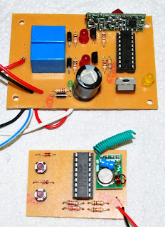
This circuit shows the system to receive and send signals to the microcontroller to turn this one-legged system. If you will not transmit or receiver of the remote, the system will not work because there is no switch 'ON' to alert the microcontroller to drive the system. picture below is an example of transmit and receiver circuit circuit for this project.
This circuit shows the system to receive and send signals to the microcontroller to turn this one-legged system. If you will not transmit or receiver of the remote, the system will not work because there is no switch 'ON' to alert the microcontroller to drive the system. picture below is an example of transmit and receiver circuit circuit for this project.
Thursday, March 29, 2012
Week 11
POWER SUPPLY
• The main component is the regulator IC 7805 which serves to convert the input DC voltage 12V to 5VDC.
• 5VDC is the operating voltage used by the PIC, sensor, relay driver, and also in the other circuits
• Diode IN4007 functions as a rectifier
• Resistor 1K ohm function as "Load" which allows a small current through it and then light the LED.
• Capasitor functioa as a "Filter" to produce a clean DC operating voltage (filtering the resulting ripple voltage)
Monday, March 19, 2012
Week10
Switching Fan Circuit
This week I make a switching circuit for the fan. This circuit was tested using MPLAB software 1st to determine whether the pairing I do right or wrong, so after all that I began to etching & soldering circuit and the result like the image below.
This week I make a switching circuit for the fan. This circuit was tested using MPLAB software 1st to determine whether the pairing I do right or wrong, so after all that I began to etching & soldering circuit and the result like the image below.
 |
| MPLAB Circuit |
 |
| Front View |
 |
| Rear View |
Wednesday, March 14, 2012
Week9
Temperature Sensor
Temperature sensor is a device used to measure the temperature of an object, in my FYP project, I use the LM35 type temperature sensor because it can detect the ambient temperature as the temperature inside a room. after the study has been made from last semester, I purchased a component to be in use and has completed this temperature sensor circuit. I attach below the circuit I have completed the picture I provided for this FYP project.
link
Temperature sensor is a device used to measure the temperature of an object, in my FYP project, I use the LM35 type temperature sensor because it can detect the ambient temperature as the temperature inside a room. after the study has been made from last semester, I purchased a component to be in use and has completed this temperature sensor circuit. I attach below the circuit I have completed the picture I provided for this FYP project.
 |
| Diagram |
 |
| Sensor LM35 |
 |
| Complete Circuit |
 |
| Front |
 |
| Rear |
link
Thursday, March 8, 2012
Week8
ULTRASONIC MOVEMENT DETECTOR
This week i research & make a circuit for Ultrasonic Movements Detector. After i get some components i buy at jalan pasar, 1st thing i do a etching for this circuit, 2nd i insert components and solder at this circuit, 3rd testing using battery for make sure it function or not, below i attach a circuit, components and complete circuit i do it now.
This week i research & make a circuit for Ultrasonic Movements Detector. After i get some components i buy at jalan pasar, 1st thing i do a etching for this circuit, 2nd i insert components and solder at this circuit, 3rd testing using battery for make sure it function or not, below i attach a circuit, components and complete circuit i do it now.
 | ||||
| ULTRASONIC MOVEMENT DETECTOR |
 |
| Components |
 |
| Components |
 |
| Rear View |
 |
| Front View |
Friday, March 2, 2012
Wednesday, February 22, 2012
Wednesday, February 15, 2012
Week 5
PIC Fan controller
This project it´s based on a
PIC16F877A, with the purpose of control a FAN
with PWM (Pulse with Modulation). It offers a
variable speed control, low acoustic noise,
reliability, long lifetime, low power
consumption, protection features. The MCU get
the temperature from the sensor (D18B20), and
after will do a conversion Celsius degrees and
then it´s generated a PWM on PORTC.2 with 6
different levels.
|
PWM
|
TEMPERATURE
|
|
15%
|
<= 49°
|
|
30%
|
50° |
|
40%
|
51° |
|
50%
|
52° |
|
75%
|
53° |
|
100%
|
>54° |
After the signal goes to
Q1 (BC338) in order to control the duty cycle in
the fan. I had to use two transistors to have an
Ic on Q2 to be enough to activate the fan.
Because the MCU only generate a maxim of 3.6V on
which output, and 15% of 3.6V is 0.5V to
polarize Q1 we need 0.7V.
How to calculate
the Q1 and Q2:

You will be
able to control the FAN between 5V and
+/-12V.The BC338 have a current load of
800mA that is value of a fan can have, you
can use two or more fans as long the current
load isn´t more than 800mA. The output of
MCU connect to the Q1 and Q2 it works like a
switch, the D3 it´s for protection from the
magnetic field in the inductors from the
FAN, without the D3 when you turn off the
system the current will be discharge to the
Q2 and could damage it.
|
Connectors
|
|
|
J1 |
Expansions PORTS |
|
Source |
12V |
|
Sensor |
D18B20 |
|
FAN |
Connect the FAN |
|
ICSP |
To program with PICKIT2 |
Pictures:
Link
Thursday, February 9, 2012
Week 4
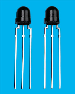
IR Receiver
 |
| IR Receiver |
This is a simple IR receiver circuit which plugs into a serial port of a computer. There are many other circuits of this kind, and most of them are even simpler, but this circuit has two major advantages:
(1) it uses an Atmel AVR RISC microcontroller (an AT90S2313) instead of the usual PIC microcontroller
(2) it uses a Maxim MAX232 for the generation of valid RS232 levels.
Advantage 1: is, of course, only valid for all those AVR addicts which have this device (and the corresponding programmer) ready at hand and don't care about PICs and PIC programmers.
Advantage 2: comes into play if the IR receiver has to placed at a great distance from the computer. The MAX232 is more likely to deliver valid signals over bigger distances than cheaper solutions.
The IR receiver can receive it's +5V supply voltage from the keyboard or mouse connector of the computer (either from an unused PS/2 port or via a pass-thru adapter). If the IR interface is placed at a great distance from the computer, I power it with an external stabilized 5V DC power supply instead of the PS/2 port.
The interface communicates at 19200 baud, unidirectional (that means, it only transmits data and does not care anything about data which the computer send), without flow control. For every level transition in the demodulated IR signal, it transmits a single byte which corresponds to the time since the previous transition, capping off at a value of 255. It works reliable with a Sony remote control (using the special Sony protocol), and I have also successfully tested it with an Onkyo remote control (I think this one uses the standard RC5 protocol, but I'm not sure). Decoding happens on the computer; I use PC Remote Control for this.
Appendix:
 |
| Infrared Receiver |
 |
| Infrared Receiver to RF Transmitter Circuit |
 |
| IR receiver sensor |
Link link2 link3 link4
Thursday, February 2, 2012
Week 3
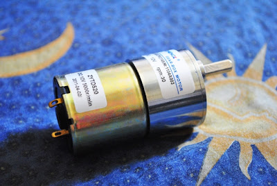
Electric Gearbox Motor 12v
Motors need to be isolated from the AVR. This is because they
produce a high voltage spike when the current flow through them suddenly
changes. This can damage the digital circuitry in the microcontroller.
To separate the Gear-Box Motor from the microcontroller we used 4N35
optoisolators. Furthermore, ULN2003 drivers are used to supply the
motor's high current needs since the microcontroller has a maximum
current rating of 40mA. The drivers contain diodes to protect the
circuitry from high voltage spikes by directing the current through the
power supply.
The motor is controlled using an 8-step sequence to halve the rated
step angle. The step sequence rate is controlled via software. The 8
step sequence not only slows down the motor but also allows more
accurate positioning of the platform.
Specifications:
1) Diameter :37mm shaft: 6mm
2) 12v Custom made speed, Torque etc
 |
| Assembling DC motor:(diameterxlength=35.8x57.0mm) |
 |
| Geared motor installation: |
Appendix:
 |
| 1 |
 |
| 2 |
 |
| 3 |
 |
| 4 |
 |
| 5 |
Wednesday, January 25, 2012
Week 2
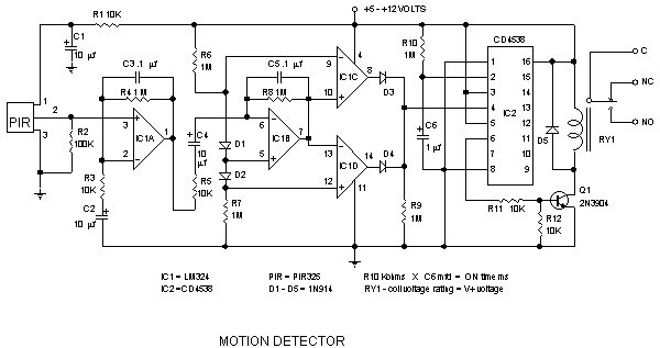
PIR Infrared motion detector Circuit
The pyroelectric sensor is made of a crystalline material that generates a surface electric charge when exposed to heat in the form of infrared radiation. When the amount of radiation striking the crystal changes, the amount of charge also changes and can then be measured with a sensitive FET device built into the sensor. The sensor elements are sensitive to radiation over a wide range so a filter window is added to the TO5 package to limit detectable radiation to the 8 to 14mm range which is most sensitive to human body radiation.
Typically, the FET source terminal pin 2 connects through a pulldown resistor of about 100 K to ground and feeds into a two stage amplifier having signal conditioning circuits. The amplifier is typically bandwidth limited to below 10Hz to reject high frequency noise and is followed by a window comparator that responds to both the positive and negative transitions of the sensor output signal. A well filtered power source of from 3 to 15 volts should be connected to the FET drain terminal pin 1
Subscribe to:
Comments (Atom)


